Thursday, November 19, 2009

Use Cases and Goals:

Actors have goals or needs, use applications to help satisfy them. Consequently,
an EBP-level use case is called a user goal-level user case, to emphasize
that it serves (or should serve) to fulfill a goal of a user of the system, or the
primary or main actor.
This is slight shift in emphasis for the use-case modeler. Rather than asking
"What are the use cases?", one starts by asking: "What are your goals?" In fact,
the name of a use case for a user goal should reflect its name, to emphasize this
viewpoint.Goal: capture or process a sale; use case: Process Sale.
Note that because of this symmetry, the EBP guideline can be equally applied to
decide if a goal or a use case is at a suitable level.


Imagine we are together in a requirements workshop. We could ask either:
. "What do you do?" (roughly a use case-oriented question) or,
. "What are your goals?"
Answers to the first question are more likely to reflect current solutions and
procedures, and the complications associated with them.
Answers to the second question, especially combined with an investigation to
move higher up the goal hierarchy ("what is the goal of that goal?") open up
the vision for new and improved solutions, focus on adding business value,
and get to the heart of what the stakeholders want from the system under
discussion.
Applying the EBP Guideline
you are investigating user goals. The conversation goes like this: During a
requirements workshop:
Requirements for use case of a system:

System analyst: "What are some of your goals in the context of using a POS
system?"
Cashier: "One, to quickly log in. Also, to capture sales."
System analyst: "What do you think is the higher level goal motivating logging
in?"
Cashier: "I’m trying to identify myself to the system, so it can validate that
I’m allowed to use the system for sales capture and other tasks."
System analyst: "Higher than that?"
Cashier: "To prevent theft, data corruption, and display of private company
information."
Note the analyst’s strategy of searching up the goal hierarchy to find higher
level user goals that still satisfy the EBP guideline, to get at the real intent
behind the action, and also to understand the context of the goals.
"Prevent theft, ..." is higher than a user goal; it may be called an enterprise goal,
and is not an EBP. Therefore, although it can inspire new ways of thinking
about the problem and solutions (such as eliminating POS systems and cashiers
completely), we will set it aside for now.
Lowering the goal level to "identify myself and be validated" appears closer to
the user goal level. But is it at the EBP level? It does not add observable or measurable
business value. If the CEO asked, "What did you do today?" and you
said "I logged in 20 times!", she would not be impressed. Consequently, this is a
secondary goal, always in the service of doing something useful, and is not an
EBP or user goal. By contrast, "capture a sale" does fit the criteria of being an
EBP or user goal.

As another example, in some stores there is a process called "cashing in", in
which a cashier inserts their own cash drawer tray into the terminal, logs in,
and tells the system how much cash is in drawer. Cashing In is an EBP-level (or
user goal level) use case; the log in step, rather than being a EBP-level use case,
is a subfunction goal in support of the goal of cashing in.

Goals and Use Cases Can Be Composite:
Goals are usually composite, from the level of an enterprise to
many supporting intermediate goals while using applications
to supporting subfunction goals within applications .
Similarly, use cases can be written at different levels to satisfy these goals, and
can be composed of lower level use cases
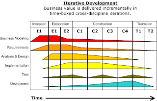
Iterative development:

Iterative development is a skillful approach to software development, and lies at
the heart of how OOA/D is presented. The Unified Process is an
example of iterative process for projects using OOA. Informally, a software development process describes an approach to building, deploying, and possibly maintaining software.
The Unified Process has emerged as a popular software development process for building
object-oriented systems. In particular, the Rational Unified Process or RUP.
RUP is an example of up.


ITERATIVE DEVELOPMENT AND THE UNIFIED PROCESS

A detailed refinement of the Unified Process, has been widely adopted.
The Unified Process combines commonly accepted best practices, such as
an iterative lifecycle and risk-driven development, into a cohesive and well-documented
description.
.UP practices provide an example structure to talk about how to do—and
how to learn—OOA/D.


Agile software development refers to a group of software development methodologies based on iterative development, where requirements and solutions evolve through collaboration between self-organizing cross-functional teams.
Agile methods generally promote a disciplined project management process that encourages frequent inspection and adaptation, a leadership philosophy that encourages team-work, self-organization and accountability, a set of engineering best practices that allow for rapid delivery of high-quality software, and a business approach that aligns development with customer needs and company goals. Conceptual foundations of this framework are found in modern approaches to operations management and analysis.
Iterative and Incremental development is a cyclic software development process developed .
Iterative Development adds agility to the development process. Divide your development schedule into about a dozen iterations of 1 to 3 weeks in length. One week is the best choice even though it seems very short. Keep the iteration length constant through out the project. This is the heart beat of your project. It is this constant that makes measuring progress and planning simple and reliable in XP.
Don't schedule your programming tasks in advance. Instead have an iterationship planning meeting at the beginning of each iteration to plan out what will be done. Just-in-time planning is an easy way to stay on top of changing user requirements.
It is also against the rules to look ahead and try to implement anything that it is not scheduled for this iteration. There will be plenty of time to implement that functionality when it becomes the most important story in the release plan.
Iteration is best way and approach for any system, because it develop the system incremently. And changes can be done in the system even latter because it is adoptive as well. It is flexible also. Thats why mostly programmers use this method and prefer it. In this methods system is divided into parts or subsystems. and each subsystem is a syatem itselfe. and each subsystem tests, construct and its own development phases.

Unified Modeling Language

The UML:
Defination:The Unified Modeling Language (UML) is a language for specifying,
visualizing, constructing, and documenting the artifacts of software systems,as
well as for business modeling and othernon-software systems.
Use cases very simple and convenient way of requirements, and these all types of diagrams are included in use cases.
UML includes a set of graphical notation techniques to create visual models of software systems. The Unified Modeling Language pushes the envelope of what can be done with existing methods..

INTRODUCTION:

Basically UML is used for graphical representation of models of systems.
The UML has emerged as the de facto and de jure standard diagramming notation
for object-oriented modeling. It started as an effort by Grady Booch and Jim
Rumbaugh in 1994 to combine the diagramming notations from their two popular methods—the Booch and OMT methods. They
joined by Ivar Jacobson, the creator of the Objectory method, and as a group came to be known as the three amigos. Many others contributed to the
UML, perhaps most notably Cris Kobryn, a leader in its rapidly increasing refinements.
The UML was adopted in 1997 as a standard by the OMG, and has continued to be refined in new
In 1996 Rational concluded that the abundance of modeling languages was slowing the adoption of object technology, so repositioning the work on a unified method, they tasked the Three Amigos with the development of a non-proprietary Unified Modeling Language. Under the technical leadership of the Three Amigos, an international consortium called the UML Partners was organized in 1996 to complete the Unified Modeling Language (UML) specification, and propose it as a response to the OMG RFP.

Modeling types:
There are different types of models :
1)Business modeling
2)Dynamical modeling
3)Logical or class modeling
4)Physical development modeling
Development Applications:
1)Reverse Engineering Java Applications
2)Creating Use Case Diagrams
3)Creating Class Diagrams
4)Creating Activity Diagrams
5)NetBeans UML Custom Code Generation
6)Synchronizing Source in NetBeans 6.5
7)NetBeans UML 6.5 Keyboard Shortcuts
These are included in the modeling of a system.

Use-case diagrams:
Use case is are written stories about system,so that user can understand the functionality of system.A use case describes a unit of functionality provided by the system. The main purpose of the use-case diagram is to help development teams visualize the functional requirements of a system, including the relationship of "actors" (the person with some activity or behaviour) to essential processes, as well as the relationships among different use cases. Use-case diagrams generally show groups of use cases -- either all use cases for the complete system, or a breakout of a particular group of use cases with their functionality and performance.


To show a use case on a use-case diagram, you draw an oval in the middle of the diagram and put the name of the use case in the center of, or below, the oval. To represent an actor on a use-case diagram, you draw a stick person to the left or right. Use simple lines to show relations between actors and use cases.

Sequence diagrams:
Sequence diagrams show a detailed flow for a particular use case or even just part of a particular use case.They show the calls between the different objects in their sequence and can show, at a detailed level, different calls to different objects like flow of messages.
A sequence flow of diagram is very simple to draw. Across the top of your diagram, identify the class objects by putting each class objects inside a box. In the box, put the class object name and class name separated by a space or colon. If a class object sends a message to another class object, draw a line with an open arrowhead pointing to the receiving class object; place the name of the message or method above the line.
Reading a sequence diagram is a very simple way. Start from top left corner with the class object that starts the sequence or flow. Then follow each message towards down the diagram.

Deployment diagram:

The deployment diagram shows how a system will be physically deployed in the hardware environment and physical representation of diagrams is a most important way that help to understand the system for user. Its shows where the different parts of the system will physically run and how they will communicate with each other. Since the diagram models the physical runtime.
The representations in a deployment diagram contains the notation elements used in a component diagram, with some additions, that also including the concept of a node. A node represents either a physical machine or a virtual machine node. To model a node, simply draw a three-dimensional cube with the name of the node at the top of that cube.
UML(unified modeling language) is a standardized general-purpose modeling of objects and is language in the field of software.

Wednesday, November 18, 2009

what is analysis and design?

Analysis:
emphasize an investigation of the problem and requirements rather than a solution .for example if a new computerized library information system is desired,how will it be used?Analysis is a broad term, be qualified, as in requirements analysis or obje analysis.

Design:
Data Structures and Algorithms with Object-Oriented Design Patterns in C++
Ultimately design can be implemented.
As with analysis, the term is best qualified, as an object design or database design.

What is object oriented analysis and design?
During object oriented analysis, there is an emphasis on finding and describing the objects or concepts in the problem domain. For example in the case of the library information system, some of the concepts include Book, Library and patron.
Basically,it is a software engineering approach that models a system as a group of interrelated objects. Each object represents some objects of interest in the system being modeled, and is known by its class, its state and its behavior. Various models in a system can be created to show the static structure, dynamic behavior, and run-time deployment of these collaborating objects.
Object-oriented analysis OOA/D applies object-modeling techniques to analyze the functional requirements for a system, elaborates the analysis models to produce implementation specifications. OOA focuses on what the system does, OOD on how the system can do that.

Define use case:
Requirements analysis may include a description of related domain processes, these can be written as use case.
Use case:
are not object oriented artifacts they are simple written stories. However they are popular tools in requirements analysis and are important part of the unified process.
For example here is a brief description of a Dice game.
"play a dice game: a player picks up and roll the dice. if the die face value total seven, the wins otherwise they lose"

Problem Domain:
Object-oriented analysis looks at the problem domain with the aim of producing a imaginary model of the information that exists in the area being analyzed. Analysis models do not consider any implementation constraints that might exist, such as concurrency, distribution, persistence, or how the system is to be built. Implementation constraints are dealt during object-oriented design. Analysis is done before the Design because it is necessary to investigate about the project or system that the user need.
The sources for the analysis can be a written requirements statement, a formal vision document, interaction with stakeholders or other necessary parties. A system may be divided into multiple parts, representing different types and works, technological, or other areas of system, each of which are analyzed and describe separately.
There are many important parts on which a software or a system depends; like
1)Interaction diagrams.
2)UML class diagrams.
3)User interface
4)Requirements
5)Construction faces

•Pattern name:
a pattern name should really reflect the meaning of what it is abstracting. It should be simple so that one can refer to it during analysis.
•Object:
A scenario that illustrates the problem and how the analysis pattern contributes to the solution in the concrete scenario
•Necessities and context:
Discussion of forces and tensions which should be resolved by the analysis pattern
•Solution:
Description of solution and of the balance of forces achieved by the analysis pattern in the scenario in the motivation section. Includes all relevant structural and behavioural aspects of the analysis pattern.
•Consequences:
this should emphasise how the goal is achieved by the analysis pattern with its limitation.
•Design:
Suggestions of design implementations of this pattern.